
Gelbo Flex Testing (ASTM F392): Barrier Foil Pinhole Guide
In barrier packaging specification, technical data sheets proudly advertise pristine transmission rates: an Oxygen Transmission Rate (OTR) of less than 0.05 cc/m²/day and a Water Vapor Transmission Rate (WVTR) below 0.05 g/m²/day for aluminum foil laminates. However, these figures are typically measured on static, unhandled, flat laboratory specimens.
In the real world, flexible pouches endure intense physical deformation. High-speed form-fill-seal (FFS) machines pull film over forming collars, pouches drop into shipping cases, and pallets undergo thousand-mile road and intermodal vibrations. Under this repetitive mechanical stress, brittle barrier layers—most notably thin aluminum foils (6µm to 9µm) and ceramic vacuum coatings—develop microscopic fractures, known as pinholes.
A single micro-pinhole measuring just 10 microns across can degrade barrier efficacy by up to 1,000-fold, causing premature spoilage in sensitive foods, pharmaceuticals, and chemicals.
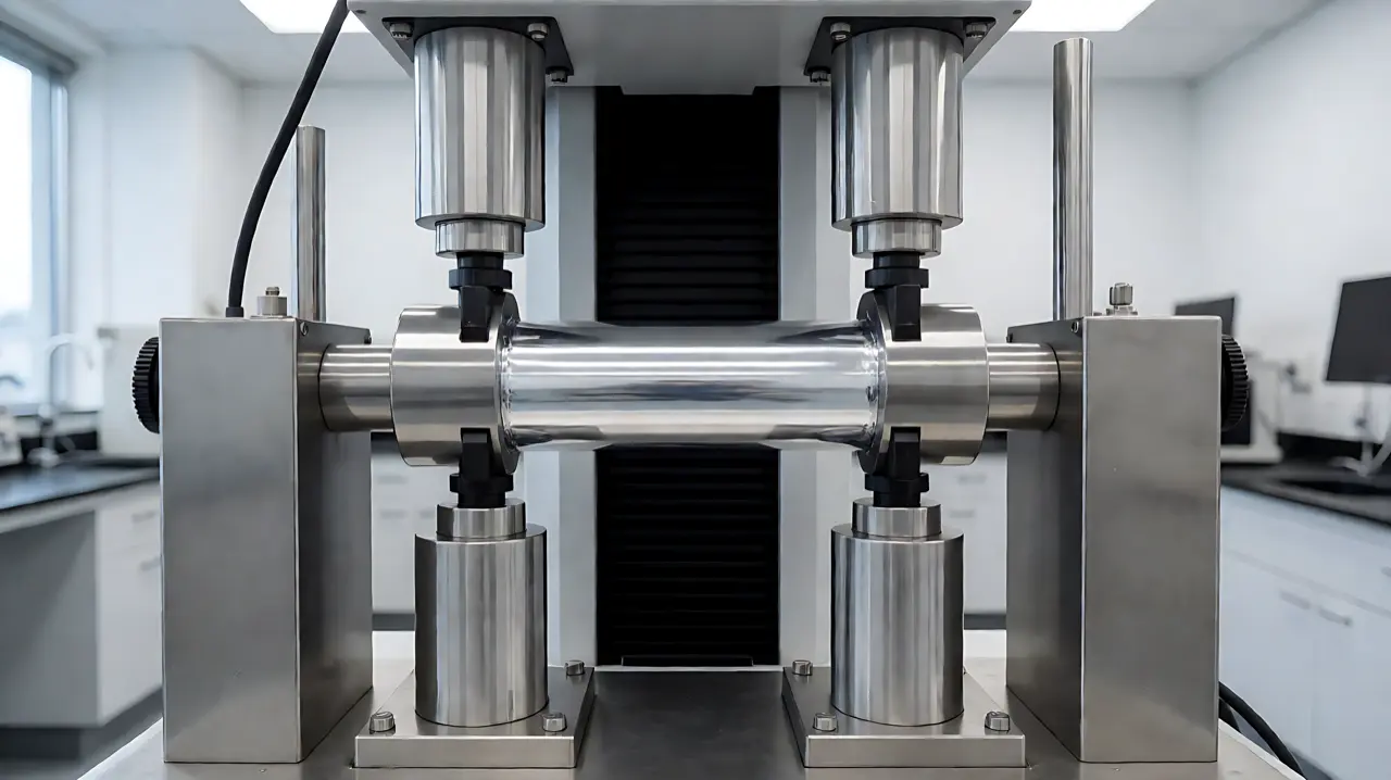
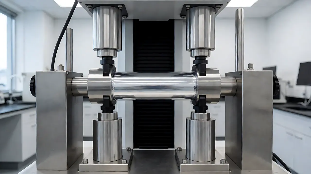
To predict and prevent transit failure, the packaging industry relies on ASTM F392: Standard Test Method for Flex Durability of Flexible Barrier Materials (commonly known as the Gelbo Flex Test).
1. ASTM F392 Testing Mechanism: Twisting & Crushing Dynamics
The Gelbo Flex tester subjects an 8“ × 11“ (200 mm × 280 mm) cylindrical film specimen to a severe compound mechanical motion:
Gelbo Flex Movement Cycle (ASTM F392):
Phase 1: Twisting Motion (440° Rotation over initial 3.5 inches of travel)
Phase 2: Compressive Crushing (Straight horizontal stroke of 2.5 inches)
Phase 3: Full Reverse Stroke back to Home Position
Total Cycle Time: ~45 complete strokes per minute| ASTM F392 Test Condition | Number of Cycles | Mechanical Severity | Standard Target Application |
|---|---|---|---|
| Condition A | 270 Full Cycles (Full twist + crushing) | Extreme Stress | Military packaging, medical devices, hazardous chemical liners |
| Condition B | 90 Full Cycles | High Stress | Heavy-duty liquid pouches, Bag-in-Box liners, export sea-freight |
| Condition C | 27 Full Cycles | Moderate Stress | Retail snack pouches, coffee bags, ambient distribution |
| Condition D | 20 Partial Cycles (Partial stroke only) | Light Stress | Cosmetic sachets, light confectionery wraps |
| Condition E | 20 Short Cycles (Crush only, no twist) | Low Stress | Rigid thermoformed pouch lidding webs |
For high-durability barrier pouches engineered to survive severe transport routes, explore our Stand-Up Pouches Category and Flat Bottom Bags.
2. Pinhole Detection Methods Post-Flexing
Once the film specimen completes its specified Gelbo flex cycles, engineers quantify barrier degradation using two primary methodologies:
1. Turpentine Dye Penetration Test (Visual Pinhole Count)
The tested film is clamped over a sheet of white absorbent backing paper. A standardized solution of purified turpentine oil dyed with 0.5% Oil Red O is poured onto the surface and allowed to dwell for 60 to 90 seconds.
- The dye solution, possessing exceptionally low surface tension (<27 mN/m), penetrates through any micro-rupture or crack.
- Technicians count the resulting red stains on the white backing paper under magnification, reporting the result as Pinholes per square meter ($/m^2$).
Pinhole Counting Visualization:
Tested Barrier Film:    [====  ====  ======  ====]
Backing Paper:          [    *     *               *]  <-- 3 Pinholes Counted
2. Instrumented Transmission Rate Degradation (OTR / WVTR)
While dye testing identifies through-thickness punctures, it cannot detect micro-fissures in internal barrier layers that have not yet perforated the outer sealant film. Advanced laboratories place the flexed specimen directly into a MOCON coulometric oxygen detector (ASTM D3985). By comparing OTR before and after Gelbo flexing, engineers calculate the Barrier Retention Ratio:
$$\text{Barrier Retention (%)} = \left( \frac{\text{OTR}{\text{unflexed}}}{\text{OTR}{\text{flexed}}} \right) \times 100$$
3. Barrier Substrate Comparison Under Flex Fatigue
Different barrier materials exhibit vastly divergent resistance to Gelbo flex fatigue:
| Barrier Structure | Unflexed OTR (cc/m²/day) | Post-20 Cycles OTR | Post-90 Cycles OTR | Primary Failure Mode |
|---|---|---|---|---|
PET 12 / ALU 7µm / PE 70 |
< 0.05 | 1.2 to 3.5 | > 25.0 (Numerous pinholes) | Metal crystalline fatigue; sharp transverse shear cracking |
PET 12 / ALU 9µm / BOPA 15 / PE 60 |
< 0.05 | < 0.10 | 0.8 to 1.8 | BOPA cushion layer dissipates shear stress; protects foil |
BOPP 20 / VMPET 12 / PE 50 |
0.8 to 1.5 | 1.0 to 1.8 | 2.5 to 4.5 | Metallized aluminum layer forms micro-craze lines; no through-hole |
BOPET 12 SiOx / PE 50 |
0.5 to 1.0 | 0.6 to 1.2 | 1.5 to 3.0 | Ductile silica ceramic network flexes without brittle fracture |
EVOH 9-Layer Coex (PE/EVOH/PE) |
0.8 to 2.0 | 0.8 to 2.1 | 0.9 to 2.2 | Bulk thermoplastic polymer chains yield elastically; zero pinholes |
4. Engineering Solutions: How to Prevent Flex Cracking
When aluminum foil or ceramic barriers must survive high Gelbo cycles, packaging engineers use several structural countermeasures:
- The BOPA (Biaxially Oriented Polyamide/Nylon) Cushion Layer: Placing a 15µm BOPA layer between aluminum foil and the inner polyethylene sealant layer dramatically enhances flex endurance. Nylon provides an exceptional tensile modulus and high elongation-at-break (up to 90%). When the laminate folds, the nylon layer absorbs the torsional bending stress, preventing the shear radius from exceeding the critical rupture strain of the aluminum crystal lattice.
- Adhesive System & Lamination Thickness: A rigid, high-modulus adhesive transfers shear stress directly into the foil layer. Conversely, using a flexible, two-component polyurethane solvent-free adhesive applied at a uniform coat weight of 2.2 to 2.8 g/m² creates a viscoelastic buffer that cushions the barrier layer.
- Optimizing Aluminum Alloy & Temper: Specify soft-temper annealed aluminum foil (Alloy 8079 or 8011, Temper “O”). Annealed foil exhibits superior ductility and elongation (>3.5%) compared to hard-temper foils, significantly delaying the onset of micro-fatigue cracking.
5. Transportation Transit Correlation (ISTA Protocols)
The Gelbo Flex test is not merely an arbitrary lab benchmark; it correlates directly with real-world shipping damage profiles:
- ISTA 3A & ASTM D4169 Random Vibration: Liquid pouches packaged in Bag-in-Box or corrugated shippers experience low-frequency harmonic resonance (3 Hz to 100 Hz) during truck and rail transport. This continuous sloshing flexes the lower corners of the inner liner millions of times.
- Corner Pinholing (Gusset Junctions): In flat bottom and stand-up pouches, the intersection where the bottom gusset folds into the side seal creates a four-ply compound bend. Gelbo flex fatigue at this specific stress concentration zone is the number one cause of commercial leakers.
6. Procurement Specification Checklist for High-Flex Applications
When ordering barrier pouches for products subjected to intensive handling (liquids, Bag-in-Box, export shipping, retort sterilization), require your supplier to provide:
- Target ASTM F392 Condition: Specify Condition C (27 cycles) for dry foods or Condition B (90 cycles) for liquids and bulk liners.
- Maximum Pinhole Allowance: Set an acceptance threshold (e.g., zero pinholes after 27 cycles; <3 pinholes/m² after 90 cycles).
- Post-Flex OTR / WVTR Ceiling: Mandate an upper boundary for post-flex barrier degradation (e.g., OTR must remain < 2.0 cc/m²/day after Condition C).
- Interlaminar Peel Strength (ASTM D1876): Verify that peel strength between foil and nylon/PE exceeds 3.5 N/15mm to prevent post-flex delamination blistering.
To engineer high-flex barrier laminations tailored to your export shipping conditions, consult the CraftPack Global materials laboratory.